Deep-FEM-UAV-Wing Dev Log (1/2): Geometry → Meshing → FEM
A practical dev log of an end-to-end pipeline: parametric UAV wing generation in Blender, tetra volume meshing in Gmsh, linear static FEM in CalculiX, and a Gradio viewer for precomputed results.
Goal: Generate 200 parametric UAV wings in Blender, create tetrahedral volume meshes with Gmsh, run linear static analysis with CalculiX, and finally inspect pre-computed results in a Gradio viewer.
0-0) 3-minute summary — What did I build?
I built an end-to-end pipeline that automatically generates 200 wings (3D), automatically converts them into FEM-ready meshes, automatically applies loads and runs analysis, and then lets you inspect the results on the web instantly.
- (Batch generation): Ran Blender in background mode to generate 200 wings automatically. A script replaces what would otherwise be 200 manual UI operations.
- (FEM preparation): Converted the 3D surface (STL) into a FEM-friendly tetra volume mesh. In plain terms: turning a “thin shell” into a “solid LEGO block” so structural analysis becomes possible.
- (Boundary conditions): Automatically defined boundary conditions: root fixed, upper surface pressure load.
- (Run FEM): Executed linear static FEM with CalculiX and saved outputs (displacement/stress) per case.
- (Visualization): Built a Gradio UI so that selecting a case immediately shows the 3D result.
Results
- Stage 1 (geometry preview): Generated 200 wings and rendered
wing_viz.glbin Gradio.
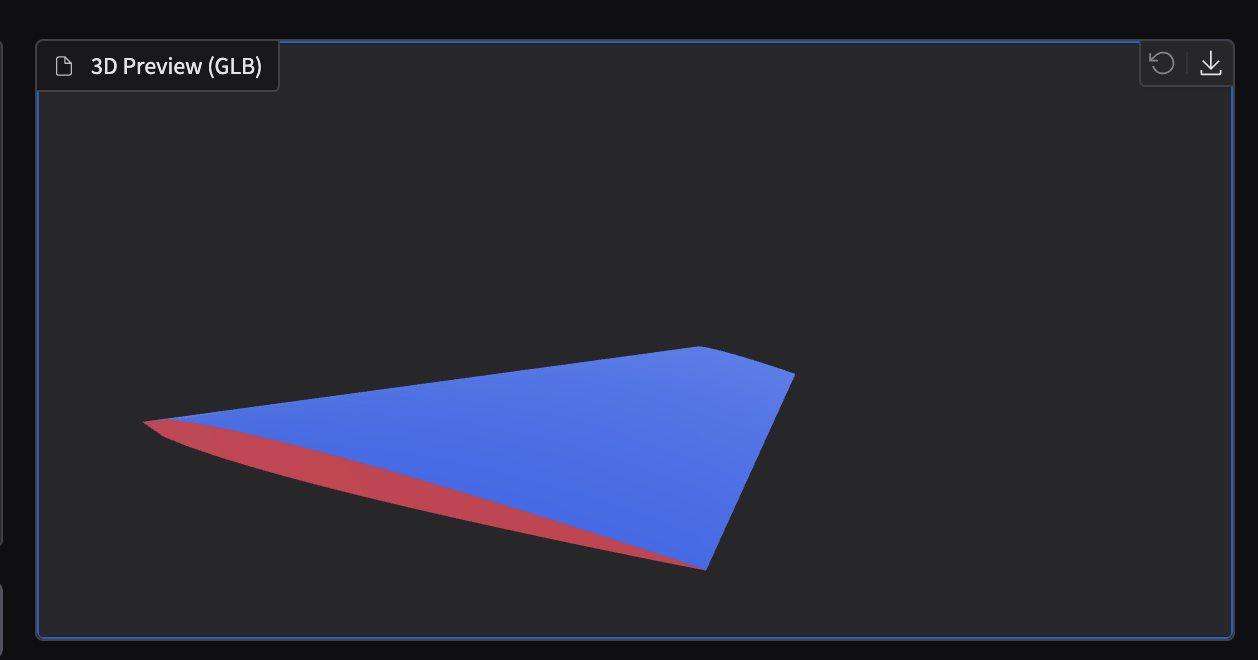
- Stage 2 (Upper/Root debug coloring):
surf_sets.glbshows that Upper/Root are correctly separated. - Upper: Blue
- Root: Red
- Else: Gray
!Stage 2 debug (surf_sets.glb)!Stage 2 debug (surf_sets.glb)
- Stage 3 (stress + pressure direction arrows): Toggle stress coloring plus sampled pressure direction arrows (200 samples).
!Stage 3 stress + arrows!Stage 3 stress + arrows ---
0) Pipeline overview
Stage 1 — Geometry generation + preview + Gradio viewer
- What is automated: Generate 200 wing geometries and also create preview assets so they can be viewed in a browser immediately.
- Inputs: Random/sampled parameters (Span/Chord/Sweep/Thickness)
- Outputs (per-case folder):
data/raw/geometry/{case_id}/ wing.stl: surface “shell” for meshing/analysiswing_viz.glb: GLB for browser previewparams.json,build_report.json: generation parameters + logs- User-visible results (Gradio):
- Select a case and preview it in 3D immediately
- Download
wing.stl - Inspect generation logs
Stage 2 — Meshing (Gmsh) + boundary set tagging + debug visualization
- What is automated: Convert STL into a solid tetra volume mesh, and automatically tag surfaces/nodes for boundary conditions (fixed/load areas).
- Input:
wing.stl - Outputs (per-case folder):
data/raw/mesh/{case_id}/ wing.msh: tetra volume meshboundary_sets.json:NROOT(fixed root)SURF_UPPER(upper surface to apply pressure)SURF_ALL(entire skin)mesh_report.json: meshing summarysurf_sets.glb: debug visualization (colored sets)- User-visible results (Gradio):
- In Meshing Debug mode, you can visually confirm Upper/Root separation
Stage 3 — FEM (CalculiX) + postprocess + result visualization (stress coloring)
- What is automated: Build solver inputs (run
ccx), then convert results into surface-aligned data + 3D assets. - Inputs:
wing.msh+boundary_sets.json+ material props (E, ν) + pressure (p) - Outputs (per-case folder):
data/raw/fem/{case_id}/ {case_id}.inp: CalculiX input (fixed + pressure){case_id}.frd: raw CalculiX resultsurface_results.npz: surface-node aligned data (coords/normals/displacement/stress/masks)wing_result.glb: 3D result with stress color- (optional)
pressure_vectors.glb,wing_result_arrows.glb: pressure direction arrows (sampled 200) - User-visible results (Gradio):
- In FEM Result, inspect the stress-colored 3D model
- Toggle Show Pressure Arrows to verify load directions
0) Python venv is required (avoid PEP 668 issues)
On many systems, installing packages into the system Python is restricted. Use a venv:
python3 -m venv .venv
source .venv/bin/activate
python -m pip install -r requirements.txt
1) Stage 1 — Generate 200 wings in Blender + STL → GLB + Gradio viewer
1-1) Batch generation (STL + GLB)
Generate 200 random airfoil-like wing shapes.
python scripts/generate_geometry_dataset.py --count 200 --seed 42Outputs (per case):
data/raw/geometry/{case_id}/wing.stldata/raw/geometry/{case_id}/wing_viz.glbdata/raw/geometry/{case_id}/params.jsondata/raw/geometry/{case_id}/build_report.json
Indices:
data/raw/geometry/params.csvdata/raw/manifest.json
1-2) Gradio shows an empty GLB viewer (JSON glTF saved with .glb extension)
Symptom: If wing_viz.glb is not a binary GLB but a JSON glTF mistakenly saved with a .glb extension, Gradio’s Model3D may render a blank screen.
Run a repair script to fix existing outputs in bulk:
python scripts/repair_geometry_glb.py
2) Stage 2 — Meshing (Gmsh) + Boundary Sets + surf_sets.glb debug
2-1) Batch meshing
python scripts/generate_mesh_dataset.py --limit 0Per-case outputs:
data/raw/mesh/{case_id}/wing.msh(tetra volume mesh)data/raw/mesh/{case_id}/mesh_report.jsondata/raw/mesh/{case_id}/boundary_sets.jsondata/raw/mesh/{case_id}/surf_sets.glb(debug: Root/Upper visualization)
2-2) Boundary set definition (core)
NROOT: node set for fixing the root (default rule:y <= y_tol)SURF_ALL: all exterior facesSURF_UPPER: subset of exterior faces on the upper surface (pressure load)- Default rule:
n_z >= nz_min - Exclude near-root region (avoid mixing boundary-condition areas)
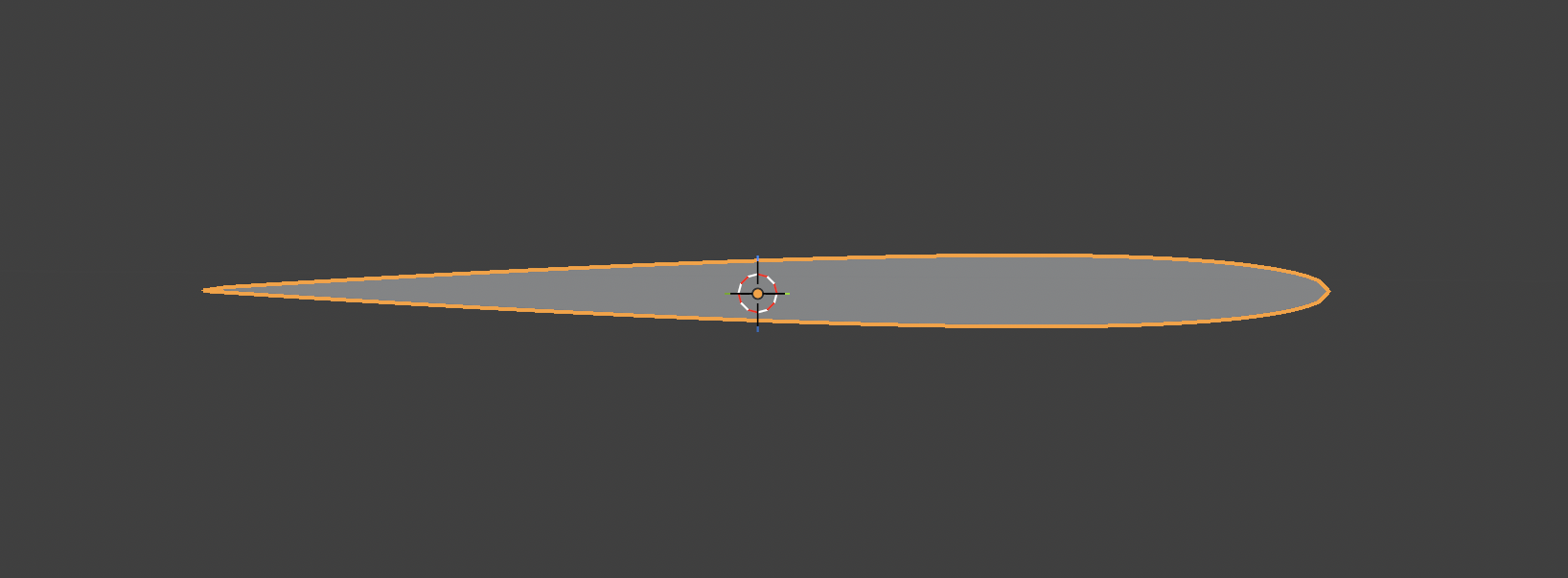
2-3) Debug colors look broken in surf_sets.glb — cause and fix
Problem: If triangle winding / normals are inconsistent, upper-surface classification becomes unstable and the blue/gray coloring looks wrong.
Fix (high-level):
- Run DFS over the triangle adjacency graph (shared edges) to make winding consistent
- Stabilize outward normals using
dot(n, C_f - C_vol)(align outward direction) - Remove “tiny fragments” in upper candidates by keeping only the largest connected component
!Meshing debug (before/after)!Meshing debug (before/after) ---
3) Stage 3 — FEM (CalculiX) + Postprocess + result GLB (stress) + pressure arrow debug
3-1) CalculiX install tip on macOS (Homebrew) — watch the ccx binary name
Homebrew’s calculix-ccx may install the solver binary as ccx_2.22 instead of ccx.
brew tap costerwi/homebrew-calculix
brew install calculix-ccx calculix-cgx
ls -la "$(brew --prefix calculix-ccx)/bin/" | grep ccx
3-3) Batch FEM execution
python scripts/generate_fem_dataset.py --limit 0 --pressure 5000Per-case outputs:
data/raw/fem/{case_id}/{case_id}.inpdata/raw/fem/{case_id}/{case_id}.frddata/raw/fem/{case_id}/surface_results.npzdata/raw/fem/{case_id}/wing_result.glbdata/raw/fem/{case_id}/fem_report.json
3-4) Pressure load application — equivalent nodal loads
Pressure on each face is converted into nodal forces and applied via *CLOAD.
- Face force:
$$\mathbf{F}_f = p \cdot A_f \cdot (-\hat n)$$
- Distribution: accumulate \(\mathbf{F}_f/3\) to each of the triangle’s three vertices.
Note:
CLOADmust be inside theSTEP block**. If it is outside, CalculiX will error.
3-5) Postprocess without ccx2paraview: parse FRD ASCII directly
ccx2paraview can be inconvenient to install. If .frd is ASCII, you can parse:
-4 DISPsection (displacement)-4 STRESSsection (stress)
…and build surface_results.npz plus wing_result.glb directly.
3-6) Pressure direction arrow debug (sample 200)
To verify upper-surface selection and load direction, sample 200 faces from SURF_UPPER and draw arrows at face centers.
Generated files:
pressure_vectors.glb(arrows only)wing_result_arrows.glb(stress + arrows combined)
In Gradio:
Preview Mode = FEM Result- Toggle Show Pressure Arrows (sampled) ON/OFF
!Pressure arrows (sampled)!Pressure arrows (sampled) ---
4) Next steps (preview)
- Stage 4: Aggregate/validate 200 solved FEM cases automatically (
nan/inf, scale sanity, failure stats) - Stage 5: Build a surface-graph dataset → train/infer AI
- Stage 6: In Gradio, show FEM vs AI side-by-side + error maps + metrics